
TOPR® UV, TOPR® WF Quartz/Quartz FiberTOPR® UV, TOPR® WF Quartz/Quartz Fiber
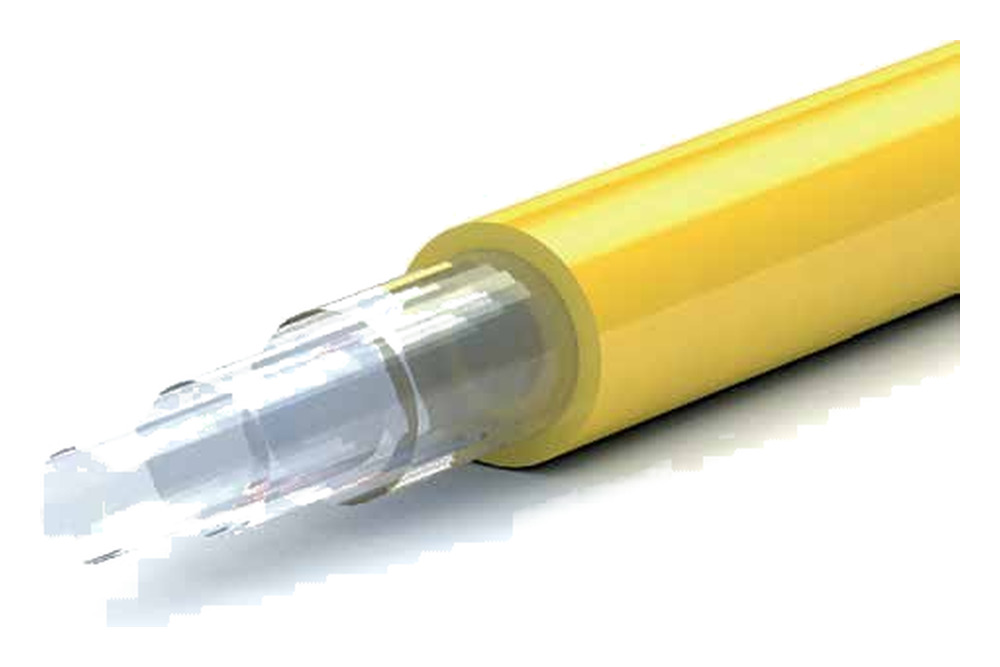
Excellent performance and fiber characteristics from ultraviolet to infrared: TOPRAYS TOPR® UV / WF fibers are available in a range of core diameters and assembly formats and can be customized to your specific application needs.
Wavelength · Numerical Aperture (NA)
| Wavelength | Numerical Aperture (NA) |
|---|---|
| TOPR® UV 190 – 1200 nm · TOPR® WF 300 – 2400 nm | Low 0.12 ± 0.02 · Standard 0.22 ± 0.02 · High 0.28 ± 0.02 |
Advantages
Pure synthetic fused silica glass core
High laser damage resistance
Step-index profile
Special jackets available for high-temperature, high-vacuum and highly corrosive chemical environments
Very low NA spread
Biocompatible materials
Can be sterilised with ethylene oxide (ETO) and similar methods
Construction
Silica glass core · fluorine-doped silica cladding · buffer layer (where applicable: silicone, hard polymer) · jacket
Jacket Options
| Jacket | Operating Temperature |
|---|---|
| Polyimide | -190 to +350 °C |
| ETFE(Tefzel®) | -40 to +150 °C |
| Nylon | -40 to +100 °C |
| Acrylate | -40 to +85 °C |
| DuPont Hytrel® 7246 | -40 to +140 °C |
| Acrylate DeSolite® DF-0009 | -40 to +150 °C |
| PFA Fluon® | -200 to +260 °C |
Technical Parameters
| Parameter | Specified value |
|---|---|
| Numerical Aperture (NA) | 0.12 ± 0.02 | 0.22 ± 0.02 | 0.28 ± 0.02 or customised |
| OH Content Options | Available on request with < 0.25 ppm and < 0.1 ppm specifications |
| Operating Temperature | -190 to +350 °C |
| Core Diameter | Available from 25 to 2000 µm |
| Standard Core/Cladding Ratio | 1 : 1.04 | 1 : 1.06 | 1 : 1.1 | 1 : 1.15 | 1 : 1.2 | 1 : 1.25 | 1 : 1.4 or customised |
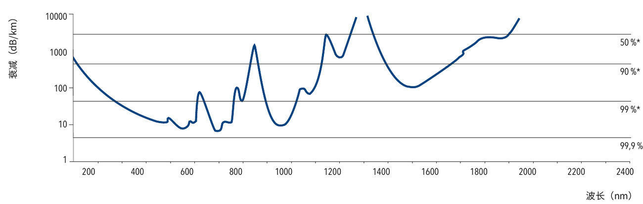
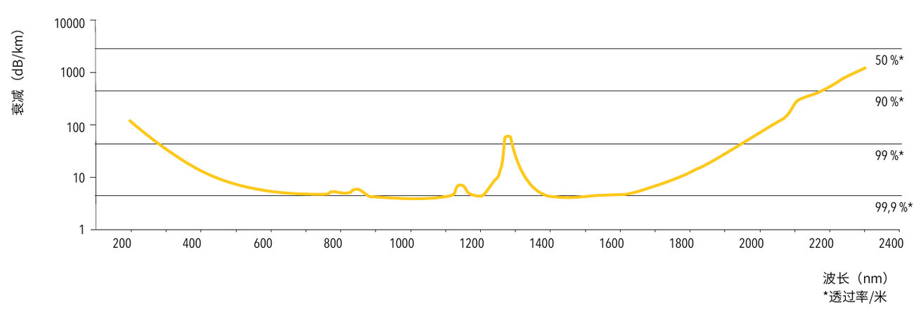
| OH Content | TOPR® UV: high (> 700 ppm) · TOPR® WF: low (< 1 ppm) · OH content < 0.25 ppm and < 0.1 ppm available on request |
| Standard Proof Test | 100 kpsi (nylon, ETFE, acrylate jackets) | 70 kpsi (polyimide jacket) |
| Minimum Bend Radius | 50 × cladding diameter (short-term mechanical stress) · 150 × core diameter (high-power laser use) |
Attenuation
The charts below summarise the attenuation at different wavelengths (right-hand scale: transmission per metre):
Applications
The preferred choice for spectroscopy, medical diagnostics, medical technology, laser delivery systems and many other applications.
Product Code Description
Example: WF 300/330 (H)(B)N (28)
| No. | Item | Code Description |
|---|---|---|
| 1 | Fiber Type | UV = TOPR® UV | WF = TOPR® WF | WFGE = TOPR® WFGE | HUV = TOPR® HUV | HWF = TOPR® HWF |
| 2 | Standard Core/Cladding Ratio | Core diameter ø (µm) / cladding diameter ø (µm) |
| 3 | Buffer layer | H = hard polymer buffer layer | unmarked = silicone buffer layer |
| 4 | Colour | B = black | BL = blue | W = white | Y = yellow | R = red | G = green | unmarked = transparent |
| 5 | Jacket Material | A = acrylate jacket (no buffer layer) | F = PFA Fluon® | N = nylon jacket (silicone or hard polymer buffer layer) | T = ETFE jacket (silicone or hard polymer buffer layer) | P = polyimide jacket (no buffer layer) |
| 6 | Numerical Aperture (NA) | 12 = 0.12 | 28 = 0.28 | unmarked = 0.22 (standard) |